ROBOWHALE TAIL
November - December 2017
While many ocean traversal vehicles take a similar mechanical form- that of a submersible with a propeller, for instance- my team proposed a craft that stands in a category of its own. Rather than utilizing a noisy and sometimes lethal propeller, we modeled our vehicle after the form and motion of a bowhead whale. In this manner, we were able to explore more complex mechanical systems and create a design able to swim among sea life without causing it disturbance. The final design is life-sized, diesel-powered, and exists only in concept.


My personal contribution to the project was the design of the vehicle’s tail. This part of the craft was intended both as a means of propulsion and a study in gearing; my goal was to use sprockets or gears to create lifelike motion in the tail based on an oscillating gear my teammate had included at its base. Conceptually, this was simple to accomplish by dividing the tail into progressively smaller segments and moving each at the same rate relative to the one before it, which caused the end of the tail to cover a much greater distance with each stroke than the base would. This method also simplified gearing, as it only required 1:1 gear ratios between segments.

Structurally, creating a geared tail transmission was more difficult. At first, I considered a chain and sprocket drive as it seemed lighter than a geared transmission. However, since each sprocket had to be offset from the last, it was impossible to apply symmetrical forces to the tail segments without using twice as many sprockets. Weight and cost shot up, and the segments had to be widened to accommodate the transmission. Using a geared transmission allowed me to build a more elegant structure consisting of parallel plates spaced just far enough apart to accommodate the next segment’s plates and gears. The rods used to space the plates also served as gearshafts and hinges between segments, and the plates left room for foam to be added within the segments’ overlapping casings to acheive neutral buoyancy.
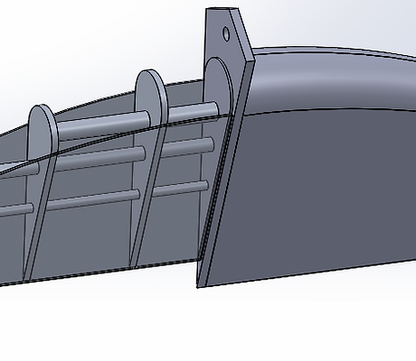
The form of the tailfin was acheived similarly to the tail segments- it consisted of a number of plates connected by spacer rods. Aluminum plates on the top and bottom surfaces allowed the fin to push against the water, and a fiberglass shell prevented water from flowing between the plates. This design also allowed for additional foam to be added within the tailfin.
The fin was not actuated by the tail transmission, or in fact powered at all; it relied instead upon the force of the water against it to create the appropriate movement. On an upstroke or downstroke, the fin was pushed by the water against stops on the last tail segment to create an angle of 30 degrees. At the top of each stroke, the fin was pushed neither up nor down and was instead forced to a horizontal orientation by the flow of the water.

As a preliminary means of analysis, I conducted some basic FEA on the most likely parts to fail. Most important was the attachment point between the largest tail segment and the gear driving it, as this junction was to effectively support the entire tail. Though we didn’t know the forces that would be acting on the tailfin, I was still able to calculate the relationship between the torque at this junction and the force applied to the fin. Since the FEA gave an estimate for the maximum forces that the junction could handle, determining whether additional support would be necessary can now easily be done for any given tailfin force.